Information
Use tidal power to give inland California needed trees. Two fully Self contained pushes of fresh water from Point Mugu to Fillmore area for one, Goleta to San Ynez area for the other.
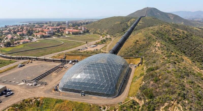
It all began with a simple idea fueled by a deep passion. A V-shaped funneled tidal catch that passes up high flowing seawater to a power turbine system. Think tree on it's side, roots in the sea via v shaped funnel structure to the trunk holding the hydro powered turbine, next the tree branches out, running water into filters, debris to be recycled, self cleaning desalinization filter getting fresh water. The flow slows, the water drops into black bottomed collection ponds, with glass roofs, yes the good kind of greenhouse. Steam is produced and sucked away by black pipelines, the tree branches going up and out. Out to the coast lands and the inlands as needed for drinking water for humans and trees.
The Adventure Phase One
MASTER COMPREHENSIVE BLUEPRINT: THE GAIA SOLUTION (Ventura County Adventure)
This 15-phase construction and operational master plan details the complete infrastructure loop from the Pacific shoreline to the agricultural valley floor, providing a direct, design guide for field engineers and workers.
Phase 1: Coastal V-Funnel Construction
* Biocement Jetty Emplacement: Pour and form dual, fanned-out rock jetties coated in marine-grade biocement on the shoreline. Lay them in a strict V-shape configuration to funnel and concentrate incoming tidal wave action directly into a centralized vertex.
* Intake Channel Stabilization: Excavate and line the narrow terminal throat canal with reinforced concrete to handle continuous high-velocity scouring.
Phase 2: Primary Marine Filtration
* Front Debris Screens: Install heavy-duty, vertical steel-mesh screens across the wide opening of the V-jetties to capture seaweed, driftwood, and large marine life.
* Self-Cleaning Mechanical Rakes: Mount automated, solar-powered scraper bars onto the trash racks to continuously clear accumulated organic matter, preventing intake blockages without restricting incoming water velocity.
Phase 3: Hydro-Kinetic Power Generation
* Bulb Turbine Installation: Mount a fully submerged axial-flow bulb hydro-turbine directly inside the narrow concrete tunnel vertex where water velocity peaks.
* Grid Connection Line: Run a direct, waterproof electrical conduit from the turbine generator housing up to a surface-level transformer pad, configured to export 100% of the tidal power output directly to the regional utility grid.
Phase 4: Kinetic Lift Incline & Elevation Initialization
* Pressure Incline Conduit: Direct the high-velocity water exiting the rear of the bulb turbine into a short, sharply rising section of heavy-walled pipeline.
* Velocity-to-Elevation Conversion: Use the remaining kinetic momentum of the incoming tide to drive the fluid up the incline, establishing a higher baseline elevation above sea level without utilizing electrical booster pumps.
Phase 5: Elevated Gravity Transport Run
* Level Transit Line: Transition the pipeline at peak incline height into an elevated, level gravity-flow line.
* Friction-Managed Inland Flow: Route this large-diameter utility line inland across the coastal flats, utilizing a slight downward slope to maintain steady, continuous transport independent of ocean pressure fluctuations.
Phase 6: Near-Shore Velocity Dissipation & Settling
* Terminal Drop Outlet: Terminate the gravity pipeline with an open-ended vertical drop that allows the saltwater to drip and fall directly into a deep, engineered Settling Pond.
* Sediment Precipitation Basin: Maintain a zero-velocity state within the deep basin to let sand, silt, and heavy suspended particulates precipitate naturally out of suspension to the basin floor.
* Secondary Fine Filtration: Install a bank of low-resistance, fine-mesh micro-filters at the basin exit channel to capture remaining microscopic particles.
Phase 7: Plain Crossing Solar Pump Relay
* Staggered Relay Stations: Erect a chain of 3 to 4 modular pump stations spaced at equal intervals across the flat coastal plain toward the mountains.
* Localized Solar Arrays: Install dedicated ground-mounted photovoltaic arrays at each station site to run standard, low-pressure utility water pumps.
* Low-Pressure Pipeline Corridor: Interconnect the stations with standard utility PVC or ductile iron piping to steadily step-pump the clean, still seawater across the flats.
Phase 8: Howard Road Terminal Setup
* Southern Gateway Basin: Construct a covered concrete receiving manifold on the flat ground on the south side of the US-101 freeway along the Howard Road alignment.
* Manifold Distribution: Configure the manifold to receive the low-pressure saltwater from the plain pipeline and distribute it evenly into the heating arrays.
Phase 9: Thermal Absorption & Containment (The Black Pond)
* 150x300-Foot Pond Excavation: Dig a shallow, wide-surface basin right next to Howard Road at the base of the mountain.
* Heat-Retentive Black Lining: Line the entire pond bed with a high-density, deep-black thermal absorption membrane to capture maximum solar irradiance.
* Insulated Glass Enclosure: Seal the entire pond structure beneath a heavy, dual-paned greenhouse glass canopy to trap ambient heat and maximize water temperature without allowing vapor to escape.
Phase 10: Ground-Level Barometric Flash Extraction
* 34-Foot Well Boring: Drill a precise, 34-foot vertical shaft straight down into the flat ground immediately adjacent to the Howard Road pond manifold.
* Barometric Drop-Leg Installation: Lower a sealed, vertical column pipe into the well to create a power-free, gravity-driven barometric vacuum chamber at the top of the column.
* Flash Evaporation Interface: Pipe the super-heated saltwater from the pond directly into the low-pressure vacuum zone, causing the liquid to violently flash-boil into pure steam at a drastically lower boiling temperature.
Phase 11: Hillside Vapor Ascent Sequence
* Light Black Tubing Run: Connect lightweight, thin-walled black vapor tubing directly to the apex of the barometric flash chamber and route it straight up the steep north face of Conejo Mountain.
* Solar Thermal Shielding: Utilize the black color of the pipe to absorb direct hillside sunlight, keeping the internal pipe walls hot enough to completely prevent premature condensation during the uphill climb.
Phase 12: Stage 1 Hilltop Suction & Condensation
* Inline Suction Blower: Mount a solar-powered, variable-speed inline suction fan directly at the top of the black tubing at the first major mountain bench (Stage 1).
* Negative Pressure Pull: Run the fan continuously to maintain a low-pressure zone at the top of the mountain line, actively pulling the rising steam up the mountain slope.
* Stage 1 Cooling Basin: Force the pulled steam directly into a shaded, wind-cooled hilltop condensation basin, flash-converting 100% of the vapor back into liquid fresh water in one centralized location.
Phase 13: High-Elevation Solar Liquid Lift
* High-Head Pump Array: Install a series of high-efficiency, solar-powered multi-stage liquid pumps at the Stage 1 basin.
* Mountain Spine Pipeline: Run a standard, heavy-duty water line from Stage 1 straight up the remaining spine of the smooth ridge to the peak saddle of Conejo Mountain.
* Liquid Relay Lift: Pump the accumulated fresh water up the final incline to secure maximum potential energy elevation.
Phase 14: The Hilltop Battery Lake
* Peak Saddle Reservoir: Excavate and construct a massive, synthetic-lined open-air holding reservoir (The Battery Lake) at the absolute mountain peak saddle.
* Potential Energy Storage: Store millions of gallons of fresh water at maximum elevation, ready to act as both a massive agricultural water bank and a grid-stabilizing energy reserve.
Phase 15: Freeway Underpass Gravity Drop & Valley Distribution
* High-Pressure Penstock Line: Lay a heavy-gauge steel penstock pipeline straight down the north face of Conejo Mountain toward the valley floor.
* In-Line Hydro Phase Turbine: Position a high-head hydro-turbine generator at the base of the penstock to capture the immense kinetic energy of the falling water during peak electrical grid demand spikes.
* 101 Underpass Routing: Route the exit pipeline safely beneath the US-101 freeway by utilizing the existing concrete right-of-ways and drainage underpasses at the Howard Road / Pancho Road alignment.
* Zero-Energy Valley Irrigation: Discharge the fresh water directly into the valley distribution grid, utilizing pure gravity pressure to irrigate the orchards, redwoods, oaks, and nut crops across the valley floor without drawing a single watt of grid power.
The Adventure Phase One plus
Goleta to San Ynez Valley. A bigger set to tightly linked projects/stations. Bore a tunnel under San Marcos pass. Plant Redwood trees and build an Airport in San Ynez valley. Build a in the ocean V funnel tidal catch in Goleta to push power and water inland, move the old airport to San Ynez valley. All using earth friendly solutions.
*1 The Tidal V shaped funnel designed to capture tidal flow and speed it up.
*2 The funnel closes around the flow to direct it's awesome power to the tubular trunk. Using Bulb turbines to harvest electrical power.
*3 In the trunk tube we throw in debris filters sending debris off for recycling.
*4 The tunnel trunk starts branching out, small debris catches for recycling, and desalinization filters for fresh water.
*5 Fresh water is dumped into black bottomed ponds with glass covers that catch the sun and heat the water.
*7 Steam produced is sucked away by black pipelines directing most steam up the hill, but some out to Goleta and Santa Bambara's water supplies.
*8 The steam piped up will be condense and be pooled in holding ponds on the hills between Goleta and San Ynez.
*9 Then as required the high holding ponds get to let water down either side through hydropower generator ,power to the grids, water directed out for planting big trees to catch catch CO2.
*10 replace the old Santa Barbara Airport with new bigger one in San Ynez Valley.
*11 Bore the tunnel using Multiple Drift Method or the Pre-Vault Method, and build the road from Goleta to San Ynez Valley.
*12 or Just 1A, Plant Redwoods and live Oak.
Step into the adventure
Stay right where you are our stop on by, but let your mind travel to Point Mugu, Camarillo, and Ventura County, California. Together, we are building the vision, the architecture, and the regenerative tidal systems that breathe life and pure water back into our landscapes.
A question about who would do that. Well all of us , What's in it for us, Answer is major gratification, that really good feeling, and our own health.
For controllers and catalytic worker we can start with the two schools. UCSB and CSUCI. But we all jump in, from children raise seedling trees, to current heroes already working eco improvement.
Harvard, Ohio State, Alabama, Texas, London, Paris, Casablanca, China, Russia, India, all you thinkers and doers.
Use your powers, find out if this helps you. Do the math, build some models, test what works for you. Our gift to you is these modular, small solutions linked together. The concept and vision is in the works.
Work the concept
A call to all universities everywhere. You can accept this adventure now, Math, engineering, communication, there are vast opportunities here. Answer and solve each question that pops up. Start building conceptual models, use AI, use the system. design and build a conceptual model on the ground at Camarillo and Point Mugu. Build the structures using Earth to heal the Gaia.
Phase one Stations one and two
*1 The Catch: Tidal underwater funnel.
*2 The funnel closes around the flow to direct it's tidal power to the tubular pipeline.


Phase one Station three
*3 In the trunk tube we throw in debris filters sending it off for recycling.
Phase one Station four
*4 The high flows go on where hydropower turbine spins off electricity and sends to a power grid.


Phase one Station five
*5 The tunnel trunk starts branching out, small debris catches for recycling, and desalinization self cleaning salt filters for fresh water.
Phase one Station six
*6 Fresh water is dumped into black bottomed ponds with glass covers that catch the sun and heat the water.


Phase one Station 9
*9 Then, as required the high holding ponds get to push it's water down either side through hydropower generator ,power to the grids, water directed out for planting big trees to catch catch CO2 in inland hills and valleys.
Phase one Station 7 and 8
*7 Steam produced is sucked away by black pipelines directing some up some out.
*8 The steam piped up will be condense and be pooled in holding pond.